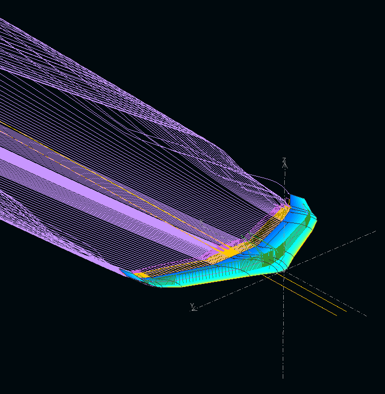
Aerodynamic & Flight Dynamic Design

Disclaimer: This one is quite long and I cannot guarantee factual accuracy. For naming conventions of variables/symbols I try to adhere to DIN 9300-1 1990 (I think the eqivalent ISO standard is ISO 1151-1).
Airfoil Profile Choice
An obviously important choice for a flying wing is the wing’s airfoil.
...
Unfortunately there is no perfect choice here.Making XFLR5 work

XFLR5 is THE program to do the aerodynamics and flight dynamics calculations with - at least as an open source solution.
Disclaimer: I’m doing everything on Ubuntu 19.04.
While there is a packaged version of XFLR5 in the package sources of Ubuntu & Debian this is REALLY old (Version 6.09.06 see here or here from 2013-12 compared to currently current version 6.47 from 2019-07-07) and had a few bugs bugging me. Three solutions for me to get a newer version:
- Compile from source
- Didn’t work for me really, as there were always errors, but I did not spend too much time on it trying to solve all problems. There are a few projects on github (or somewhere else), which try to provide working compile scripts, which also did not work for me.
- Compile from source
Cut Reinforcement Test
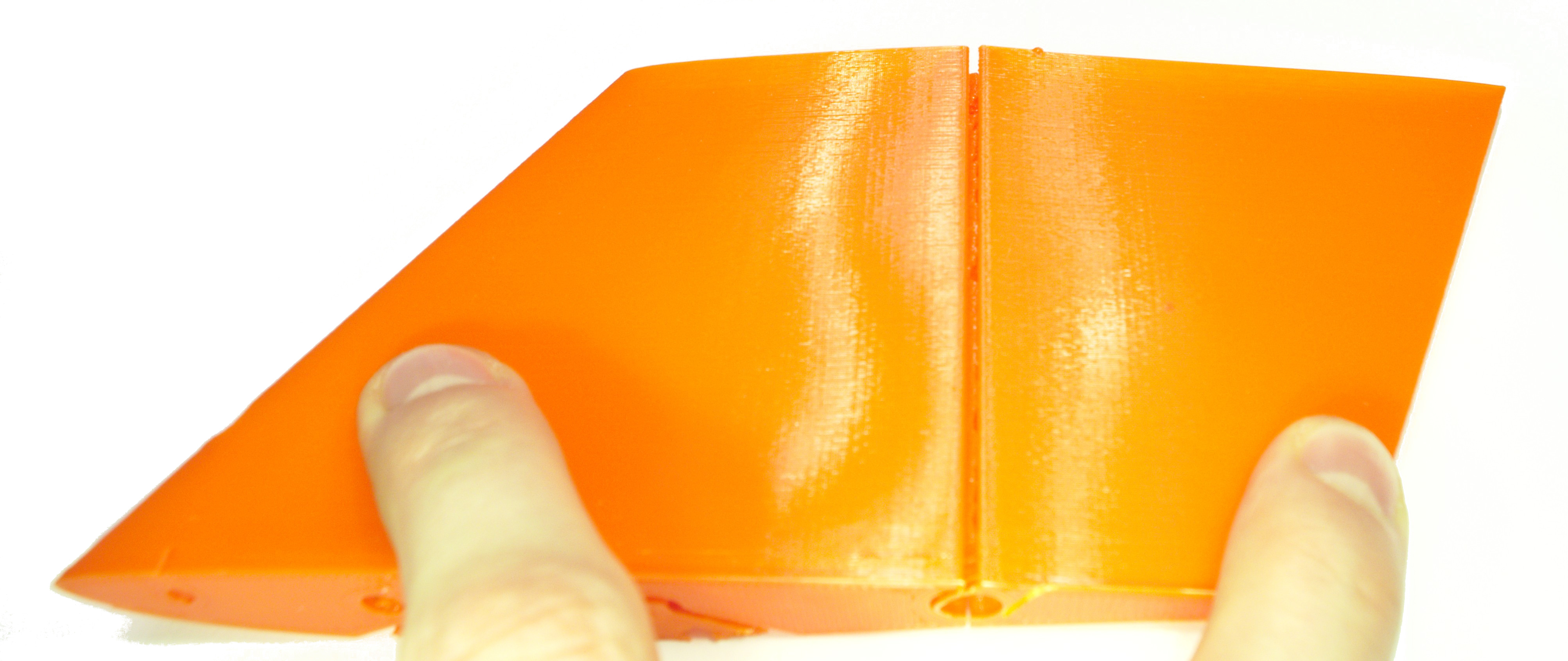
 This cut perpendicular to layers did not work at all - or rather it did work as it did cut, but both sides of the cut did not fuse together as intended
The idea was, to add reinforcements to 3d printed parts by making minimally thin cuts into the part. This technique works quite well with thick parts, I did that. By making a small slice into the 3d part, the slicer then obviously sees walls and adds wall lines accordingly - adding structure to the part without interfering with infill. This also worked for me here, but ONLY with the horizontal cuts to create ribs in the wing. Structural reinforcements in the wing around the spar did not work at all, but created exactly what I constructed in CAD - a cut. In hindsight this sounds obvious, but again - it works for parts with thicker walls, but I only want one wall line due to weight.
...Can this work at all? 3D print weight test

For hand launch, my personal insurance and the plane’s general ability to fly sensibly, the mass of the airframe, as constructed must be minimized. With this test wing, according to Cura, the mass of this 180 mm by 180 mm wing segment is around 45 g, bringing the whole wing weight to ca. 150 g - works for me.
...Original Construction ideas

- Manufacturing technique fixed as FDM
- Restrictions of FDM:
- Fixed maximum size: ~190x190x190mm³ bounding box
- Wing needs to be printed in parts, parts need to be connected stabily
- Highly anisotropic material -> Parts brittle perpendicular to layers
- Rough surface perpendicular to layer lines
- rough parts approx. along airflow
- “low resolution” in z (-> Layer height)
- Wing must be printed vertically with layer = xy-plane
- Reinforcements can be made by constructing very slim Cuts into the model. On Both sides of the cut the Slicer will create wall lines, thus adding additional plastic in places needed
- Useful with reinforcements for wing spar, and screws
- Create ribs by making a cut through the wing
- Fixed maximum size: ~190x190x190mm³ bounding box
About this blog
This blog will show my progess with creating a 3d printed model airplane. As I got the idea for this website some time later in the progress of this project, so some of the posts are logically behind the plane CAD etc. in the repository.
However, if you cannot wait for the posts, feel free to look into the plane design repository.
Of course, contributions are welcome as well.
...
