Aerodynamic & Flight Dynamic Design

Disclaimer: This one is quite long and I cannot guarantee factual accuracy. For naming conventions of variables/symbols I try to adhere to DIN 9300-1 1990 (I think the eqivalent ISO standard is ISO 1151-1).
Airfoil Profile Choice
An obviously important choice for a flying wing is the wing’s airfoil.
Unfortunately there is no perfect choice here.
As for everything…
There are several important factors to consider:
- Aerodynamic factors:
- Lift-to-Drag-Ratio - \(\frac{c_l}{c_w}\) respectively \(\epsilon\) or its reciprocal value \(E\)
- Well, there are very few engineers, who are not interested in Efficiency. For a model airplane efficiency impacts flight duration, glide path angle, “Eigensinken” (true descent - if anybody knows the correct English term? -> slowest possible descent rate without external influences & motors)
- Maximum Coefficient of Lift \(c_{l, max}\)
- Important for the slowest possible flight speed - important for hand launch
- Ideally no sharp drop off in \(c_l\) beyond \(\alpha_{max}\) - don’t want to suddenly lose all lift
- Low \(c_w\) in an \(\alpha\) range rather than a little spike as sometimes seen with laminar profiles
- Rather guesswork:
- Do little disturbances in profile shape/surface quality impact aerodynamic properties more or less? - less is preferably due to imperfections through FDM process
- Do flaps work well with respective airfoils?
- Can the airfoil be printed well? (Constant curves preferably)
- Lift-to-Drag-Ratio - \(\frac{c_l}{c_w}\) respectively \(\epsilon\) or its reciprocal value \(E\)
- Practical considerations:
- “Fuselage” part must be thick enough to provide space for battery & electronics. There will be a small fuselage kind of part, as I want a replaceable nose part and I need space for a motor. Close to that fuselage I want a really thick airfoil (around \(15 \% d/l\)) for aesthetic reasons.
- Thick enough for a metal or carbon spar
- Doable in FreeCAD
- Flap will be printed with a flat bottom surface, thus trailing edge should not be curved
- Form stability - round-ish forms are a bit more form stable (mostly was not considered)
Flight Dynamics
- For stable flight the sum of all moments of force must be zero
- Longitudinal Stability.
- Generally, for planes the center of gravity should be located in front of the wing’s center of pressure. Thus, without further influences the plane would pitch down (German Wikipedia has a nice longer explanation de.wikipedia.org/wiki/Weight_and_Balance, but I did not find an English equivalent). To counteract this pitching moment, the horizontal stabilizer creates a downwards force, also counteracting a bit of the wing’s lift and creating drag. In a stable condition, with a change in pitch \(\phi\) (and Angle of Attack AoA) a counteraction moment is produced \(\frac{\partial C_m}{\partial C_\alpha} < 0\). See en.wikipedia.org/wiki/Longitudinal_static_stability..
- With flying wings there is no tailplane, thus there are potential problems with longitudinal stability.
- Solutions:
-Wing Swept back, Angle of Incidence AoI lower in the outer regions of the wing (-> in the back), acting like a tailplane. See en.wikipedia.org/wiki/Tailless_aircraft - IMHO a really good article.
- Airfoils with low pitching moments
- Yaw stability.
- Similar problem as for longitudinal stability - neither is there a vertical stabilizer. Not directly given as a graph of partial derivatives in XFLR5 so it’s a bit of guesswork.
- Solutions: See en.wikipedia.org/wiki/Flying_wing
- Wing Sweep
- Reduced AoI at the tip is supposed to help
- Fins at the tip
- A Good read on stability, which I saw too late: http://www.xflr5.tech/docs/XFLR5_and_Stability_analysis.pdf
Flight Characteristics
- Gentle stalling characteristics - no tip stall - stall first in the middle of the wing
- Lower AoI at wing tips & profile stalling at higher \(\alpha\)
- No adverse Yaw
- Wing twist is supposed to help?
- Different deflection angles for elevons up/down for roll might also help?
Useful things
- Airfoil Database
- Another Airfoil Database
- SHORT XFLR5 Walkthrough
- Flying Wing Design Help - Really good, but GERMAN
Proposed Solution
- Airfoil Choice
- According to aerodesign.de I chose a thicker profile (S5010) and modified it regarding thickness (even thicker) in the inner wing parts, which should work according to XFLR5
- Should be good regarding moments
- I put quite a bit of thought into the profile choice and then still ended up using the one suggested by aerodesign.de… Well, I’m an engineer, I should be okay with just believing literature ¯\_(ツ)_/¯
- For comparison I also took the Clark-Y profile & S5020
- You can see profile data at:
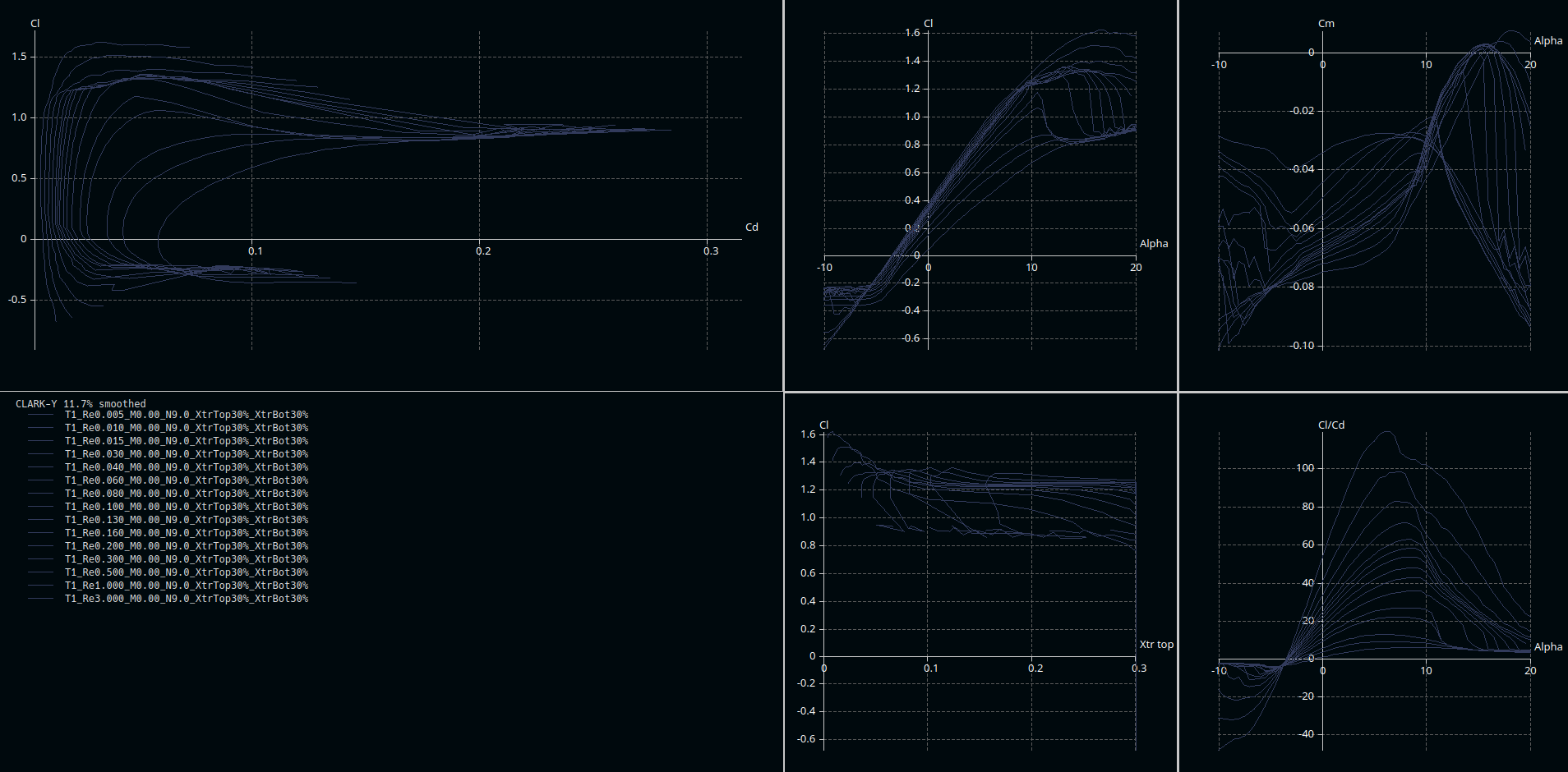
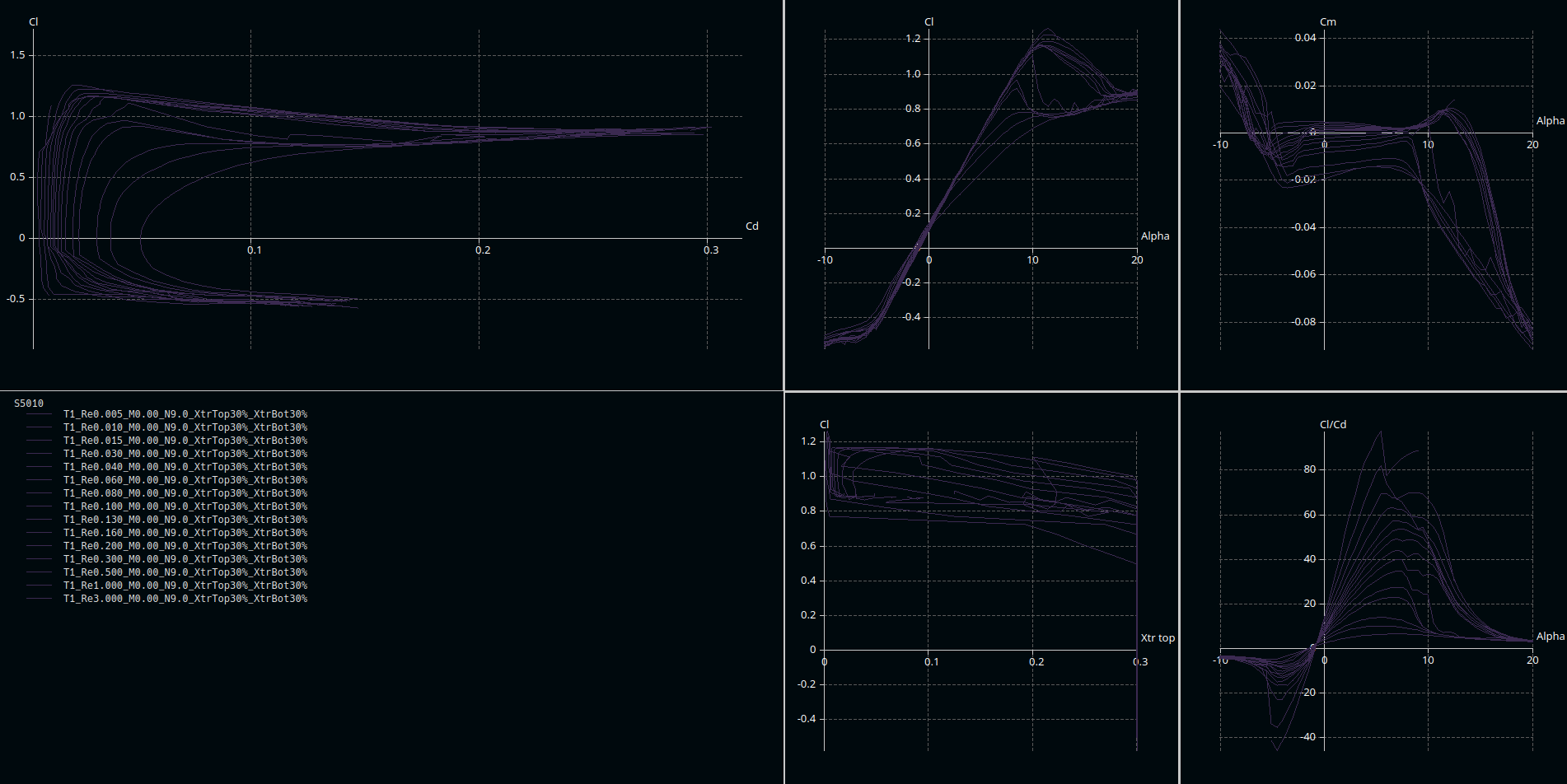
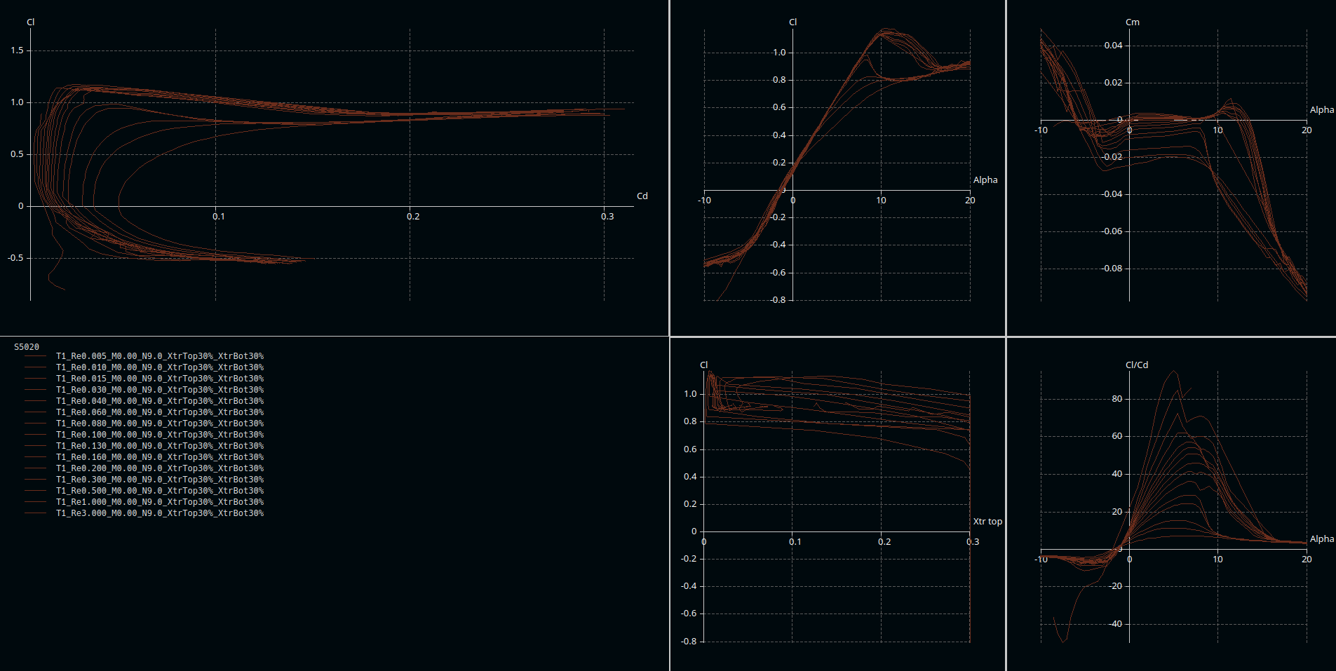
- What can be seen in that comparison:
- \(\mid C_m \mid\) a lot lower for S5010
- \(C_{L, max}\) better for CLARK-Y -> thicker
- As CLARK-Y is thicker, the drop off for \(C_a\), when stalling, is more gentle
- Here the data provided by airfoiltools.com is more in concordance with what I learned at university - XFLR5 still shows a lot of lift beyond stalling - maybe this is calculated with a lift vector rotating with the airfoil?
- \(\frac{C_L}{C_D}\) plateaus for CLARK-Y, has more of a peak for S5010 - generally I would like that plateau better, but as explained before, moments are more important for a flying wing
- \(C_m\) for S5010 lowering beyond stall AoA - pitch down, when stalling, should be nice
- You can see profile data at:
- According to aerodesign.de I chose a thicker profile (S5010) and modified it regarding thickness (even thicker) in the inner wing parts, which should work according to XFLR5
- Wing
- Planform
- For stability reasons the wing must be swept - I went with around 30° as an average over a lot of google searches and forum guesstimates - also I think it does look nice this way :)
- Lift Distribution & twist
- For a Flying Wing a bell shaped lift distribution is recommended. To calculate a lift distribution, the design lift force is necessary (which I don’t know exactly) and the design speed (which I don’t know at all)
Sooo… Precision guesswork - or rather asking the internet
… which answered me -2.0° - Maybe I will revise those design choices later on, but for the first iteration that’s it.
- For a Flying Wing a bell shaped lift distribution is recommended. To calculate a lift distribution, the design lift force is necessary (which I don’t know exactly) and the design speed (which I don’t know at all)
- Winglets
- I will write a post on winglets, but for now the answer is, that I will have “winglets” with 45° dihedral for printability & 2.5° twist.
- Planform
Results
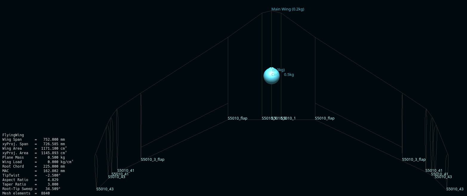
That’s a wing in software, I have no idea, how it performs in reality.
For me the most important factor for this analysis is longitudinal stability and a first value for the CoG. According to XFLR5 the wing is still stable for the CoG in the picture above, as can be seen polar graph below: \(C_m = 0\) for \(\alpha = 4°\) and a falling curve for \(C_m\). If anything, it might not be easy to get that CoG that far back, but this will be trial and error also.
For yaw stability & dutch roll even more quesswork is involved. PROBABLY the wing sweep should provide yaw stability. But, with a lot of surface area in front of the CoG, the Fuselage is an important factor for longitudinal and yaw stability, which is not accounted for in XFLR5 per its programmer himself. So it’s hoping for the best. In case of instability I would probably add a vertical stabilizer to the fuselage and/or wing fences, as advised by RCModelReviews.
I did the XFLR5 stability analysis anyway (without fuselage): Well… It told me, Dutch Roll has a positive real value for it’s eigenvalue and, thus, is unstable :( An considering my guess, that the fuselage will make stability worse, I will try to modify the plane to make it more stable (without wing fences first).
A short introduction to the root locus diagram for normal modes in aircraft. The root locus is a tool from control theory and can provide information regarding stability, damping, and frequency of a normal mode.
In the plane’s case the most important factor is: I want that to be stable. I want EVERYTHING around that to be stable without additional controllers. For something to be stable in the root locus diagram the real part of the complex number representing the normal mode must be \(<0\).
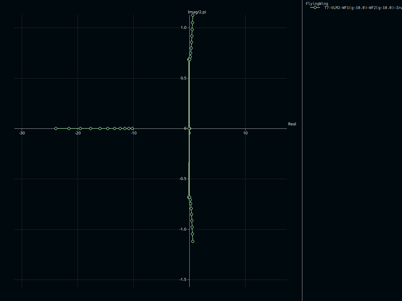 That's how it's not supposed to be like. Somethin right of 0 = bad.
Next Iteration
According to a paper the dihedral angle might increase the dutch roll instability.
Thus I removed the “Winglets”/45° dihedral wing tip areas and basically went on with the 20° dihedral, which I had for screwing together reasons and for roll stability, up to the wing tips.
Still unstable :( But VERY slightly unstable. The internet could not provide me with a nice solution unfortunately. The only solution provided is adding more directional stability by adding some sort of fin (not fins as winglets). I’m providing some more graphs below, with & without stabilizers.
Another Interation
I did add stabilizers & they do, what they ares supposed to. Construction wise, I added them in between two printed parts, so that I can change, remove & add them, if I do not like the handling characteristics.
This is what it looks like now:
Data first (xflr5 screenshots):
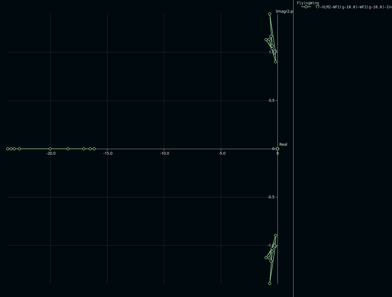 Nothing right of 0 now.
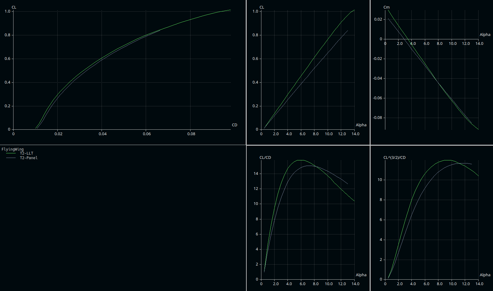 Those are the polar graphs.
Is this any good?
I don’t know. I did not find many comparisons online.
This is something I found, but unfortunately without the xflr5 file. Both designs have better \(L/D\), but this is to be expected with higher aspect ratio wings, which I cannot do due to the 3D-Print construction. Well, more info would be appreciated.
A the preliminary areodynamic design I will work on the next steps with these results - 3D-printable construction in FreeCAD!

Comments
No comments found for this article.
Join the discussion for this article